
As a Project / Site Engineer, GPS Manager, Surveyor or Site Supervisor or as someone that supports these users in their work we provide a range of tools that will assist you to create, manage, deliver, receive and process data to create required field files, reports and deliverables.
Your role will inevitably incorporate some elements of Data Management (for 3D Machine Control or Survey) and Equipment Management (to track / check materials moved, imported or removed from site) and productivity / performance management (to track / check cycles, loads, performance metrics and equipment utilization).
You also require knowledge and know-how relating to file formats, data structures, field techniques, raw and coordinate data, coordinate systems and site calibrations as well as best practices for best field system performance.
Our resources libraries provide you with Custom Menus, Toolbars and Shortcuts to improve your workflows, Project and Drafting Templates to get you started and provide drawing creation automation for Plans, Profiles, Sections and Custom Sheet Layouts in addition to providing you with Materials Libraries and a structured workflow to get the job done.
Our Training and Support program will train your users how to use TBC and how to execute the 3D Modeling / Data Prep and Field Data Management workflows, accelerate your learning and user development to get results quicker and with increased accuracy.
We are here to help you – our team has decades of Trimble Business Center and Trimble / 3rd Party Field Systems experience, we know how all this works and we can show you the best way to get optimum results on site and in your reports and deliverables.
Creates a formatted Excel Spreadsheet report from measured 3D points aligned to specified station intervals against a line or alignment, sorted from Left to Right across the alignment where each column of data is a specified code and the value presented is the Delta Elevation between the measured point and the referenced surface elevation.
Generates a Cut Sheet Report for Project Supervisors that shows full cross section details of slope, elevation, offset, delta elevation and cut/fill for user selected nodes of a corridor cross section material layer surface e.g. Finished Grade. The report generates a section at every defined interval plus all critical locations (PC, PT, VPI etc.) as well as every table and superelevation instruction location.

Creates and opens a CSV report in Excel that tabulates a custom selection of values relating to the selected points including local and global coordinates, feature codes, attributes, media files, station, offset, slope and delta elevations to lines, delta elevations to surfaces, siurface slope and direction and more. Feature codes are grouped and reported based on common attribute sets for easy reading. Custom reports can be created and saved for reuse in any TBC project.
Create and manage boundaries, boundary collections and boundary groups. Compute and store volume calculations for later recall. Label and annotate drawings with volume labels and tables and generate volume reports for a variety of volumetric scenarios e.g. Stockpiles, Progress, Cut / Fill, Pay Quantities etc.

Reports the plan and slope areas for cut and fill broken down by specified slope ranges on each of two surfaces. The report uses the isopach computed between the two surfaces (e.g. Existing and Subgrade Adjusted Finished Grade) to determine cut and fill areas and then sums the areas of triangles of both surfaces that fall within the defined slope ranges within the computed cut and fill areas. Ideal for the determination of surface finishing / trim areas in fill scenarios.
Utilizes the RPS New Layer control to create a new layer, new layer group and assign layer properties including the takeoff categorization, potential site improvement or surface boundaries and associated site improvement attributes.

The RPS Relayer command provides increased productivity when relayering CAD objects to a number of different layers. The user can establish any number of target layers and then simply select the objects to relayer, tag the layer that they want to move them to and OK to execute. The fact that you can relayer to multiple layers quickly and easily can take significant time out of data prep processes.

Utilizes the RPS New Layer control to create a new layer, new layer group and assign layer properties including the takeoff categorization, potential site improvement or surface boundaries and associated site improvement attributes.

The RPS Relayer command provides increased productivity when relayering CAD objects to a number of different layers. The user can establish any number of target layers and then simply select the objects to relayer, tag the layer that they want to move them to and OK to execute. The fact that you can relayer to multiple layers quickly and easily can take significant time out of data prep processes.
Create multiple copies of any objects quickly on the same or different layers, in 2D or 3D and in any view

Provides manual and fully automated methods to join CAD or PDF vector lines together quickly and easily. Solves common problems like line gaps, overlaps, crossovers, lateral gaps, lines on different layers, lines with different names or colors to provide an extremely fast way to join lines. Line segments can be selected in the most convenient location not just at the ends that you wish to join.

Provides the ability to create points for stakeout on lines and alignments at intervals, extra stations, key locations, high and low points, radius points and more.

Creates points through input of station and offset values with respect to a selected alignment. Elevations can be entered using Elevation, Delta Elevation or Cross Slope from the selected alignment.

Provides manual and fully automated methods to join CAD or PDF vector lines together quickly and easily. Solves common problems like line gaps, overlaps, crossovers, lateral gaps, lines on different layers, lines with different names or colors to provide an extremely fast way to join lines. Line segments can be selected in the most convenient location not just at the ends that you wish to join.

Creates points through input of station and offset values with respect to a selected alignment. Elevations can be entered using Elevation, Delta Elevation or Cross Slope from the selected alignment.

Creates points through input of station and offset values with respect to a selected alignment. Elevations can be entered using Elevation, Delta Elevation or Cross Slope from the selected alignment.

Imports boring log data from a CSV file to create site (Takeoff) boring logs in order to rapidly build strata layers for earthworks quantity purposes.

This command creates a legend of site improvements applied to surfaces within the project either for takeoff or data modeling purposes. The legend shows the color of the site improvement and the material layer stack and defined material thicknesses for each site improvement used. This automates the creation of drawings for submittals or for use by site personnel to understand a project.

Exports selected linestrings and alignments as 3D curvilinear alignments to LandXML format for use in Trimble Access and Leica stringless paver systems.

Create point cloud regions quickly from imported point clouds using predefined boundaries.

Processes Point Clouds to intelligently reduce the number of points in the point cloud using spatial analysis techniques that retain the integrity of the source data in the resulting point cloud scan. Inclusion and exclusion boundaries can be applied to eliminated unnecessary. Also creates surface(s) from the resulting data set that can also utilize the same boundary lines for inclusion / exclusion areas. Removes vegetation (Trees, Bushes, Shrubs and Grasses from Point Cloud Data to make clean usable surfaces for project quantities.

This command provides additional drafting capabilities to label point values, delta elevations, slopes, station and offset to selected reference linestrings, alignments or surfaces for construction QA and As Built drawing creation purposes. The command also provides the ability to enter a High and Low tolerance in order to color code the text labels based on their High, Low or in Grade status.

Copy data from one project to another or within an existing project using our virtual VCL file via the Windows clipboard. Ideal for creating copies of sheet sets complete with all settings within a project or for transferring information from one project into another without having to use Export and Import processes.

Paste information from the Windows clipboard directly into your project drawings. Use with your favorite Windows clipping tool (Snagit, Snip and Paste etc.) to capture PDF sheet details, excel spreadsheet tables, images, text or virtual VCL data generated using RPS Copy to Clipboard command.

Label selected lines with names, slopes, lengths, elevations, stations, offsets, elevation deltas to a reference surface at intervals along the line or in relation to a selected reference line. Labels can be exported to machine files to assist operators on site. Labels can be staggered to avoid overwrite of text in graphics / CAD.

Compute polynomial best fit lines through points for regrading surfaces for solar farm array tables (Pre Piling).

Provides ability to create user defined pile definitions for Solar Farm piling operations to be used with RPS piling command capabilities.
Customizable importer for spreadsheet data for Solar Farm Pile Plans and Piles to automatically create Pile design data ready for machine control or QA analysis. Also imports As Built Pile data from machine files (in Excel format) and Survey QA Data for measured check points on each pile (in Excel format).
Creates a multi tab Excel report on all quality metrics for solar farm piling operations. Integrates pile designs with As Built Pile results from machine data and as built survey information to analyze 6 quality metrics for every pile.

Exports selected linestrings and alignments as 3D curvilinear alignments to LandXML format for use in Trimble Access and Leica stringless paver systems.

Compares a selection of 3D measured points to a 3D surface model and determines the shortest perpendicular distance between each point and the surface model. This is a great tool to check measured point data against a design surface for cuttings where the walls of the cutting are steep or near vertical. Generates an Excel report and 3D vector linework showing the computed distances.

Creates a CSV output that reports a selection of points and compares them to a surface and optional alignment and incorporates the points description, layer, point name and attribute information. The cut and fill between the points and surface is also reported.

Created to support production data from Leica machine control systems, this command allows the user to find the first, last, highest and lowest points in each grid cell from imported data files based on a defined grid pattern (origin, orientation, row and column spacing). The selected data is layered into separate layers so that it can be used to create different surface models.
Point clouds can be used to create surface models. The resulting surfaces can be large and are hard to report for QA / QC purposes. This command converts a TIN surface, optionally clipped to a boundary into a grid of points based on a regular or alignment based grid, and computes cut / fill values to a reference surface with applied high and low tolerances for reporting purposes.

Provides the ability to use voice input to execute any TBC command. This improves productivity and allows the commands to execute as well as the command dialog to be navigated without mouse movement.

Copies a layer group and all the layers (that have members) into a new layer group where the group and each layer is named using the existing name with an added prefix or suffix.

Copies a layer group and all the layers (that have members) into a new layer group where the group and each layer is named using the existing name with an added prefix or suffix.

A simple editing tool to add additional segments into an existing linestring. Simply click where you require additional nodes and the linestring selected updates by adding additional segments into the existing linestring. You can use this command to insert segments into the line or to add segments at either end of the line.

Create 3D linestrings quickly without the complexity of the Linestring Editor.

Switch text properties between two selected text objects. Text properties include height, width, text, rotation, oblique angle, justification, aspect ratio, layer, color etc.
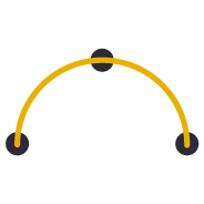
Provides the ability to create best fit 3D arcs on planes defined by three 3D points. Great for Architectural detailing from points measured with Total Stations or Scanners.

Computes points along a selected 3D line using a table of variable slope distances as the divisor. A good tool for rapidly creating building grid layouts.
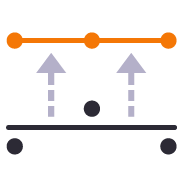
Provides the ability to move selected survey points onto even station locations within a move tolerance for reporting purposes.

Creates points through input of station and offset values with respect to a selected alignment. Elevations can be entered using Elevation, Delta Elevation or Cross Slope from the selected alignment.

A simple editing tool to add additional segments into an existing linestring. Simply click where you require additional nodes and the linestring selected updates by adding additional segments into the existing linestring. You can use this command to insert segments into the line or to add segments at either end of the line.

Create 3D linestrings quickly without the complexity of the Linestring Editor.

Provides the ability to create best fit 3D arcs on planes defined by three 3D points. Great for Architectural detailing from points measured with Total Stations or Scanners.

Creates points through input of station and offset values with respect to a selected alignment. Elevations can be entered using Elevation, Delta Elevation or Cross Slope from the selected alignment.

Provides the ability to move selected survey points onto even station locations within a move tolerance for reporting purposes.
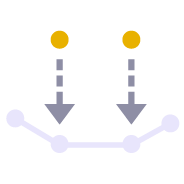
Creates a profile in the alignment profile view for a corridor that shows the delta elevation between a selected 3D line and the selected corridor material surface layer e.g. Finished Grade. Used as a check between survey data and a selected corridor model or to determine the variance of cross slope along an alignment based on survey information.

Creates points through input of station and offset values with respect to a selected alignment. Elevations can be entered using Elevation, Delta Elevation or Cross Slope from the selected alignment.

This command creates a legend of site improvements applied to surfaces within the project either for takeoff or data modeling purposes. The legend shows the color of the site improvement and the material layer stack and defined material thicknesses for each site improvement used. This automates the creation of drawings for submittals or for use by site personnel to understand a project.

Create point cloud regions quickly from imported point clouds using predefined boundaries.

Compares a selection of points to a point cloud region or scan to determine the nearest scan point to the selected points, and provides a comparison between the derived point pairs. This is a useful tool to compare measured ground check points with computed point clouds from drone surveys to validate drone survey accuracy.

One click access to Getting Started instructions for the RPS Command library

One click access to the Rockpile Solutions website

One click access to the MyRockpile Community forum

One click access to the MyRockpile Library for all your training needs

Upcoming training opportunities with Rockpile Solutions

One click access to the Rockpile Solutions LinkedIn page

One click access to the Rockpile Solutions YouTube page

One click access to the Rockpile Solutions Instagram page

One click access to generate a Support Ticket for RPS staff assistance

The Contact Us command allows you to raise a question to Rockpile Solutions staff directly from inside Trimble Business Center.

Track and manage the installation and update of registered RPS commands

Manage your global RPS command settings

Show the direction of a selected line

Toggle between light and dark Mode menu color schemes

Access to Rockpile Solutions Online Help System.

Creates and manages TBC keyboard shortcuts for commands and provides the ability to save different shortcut definitions into settings files for easy recall.

Utility that provides the ability to save out your custom toolbars and import them back into a different menu configuration

Provides the ability to use voice input to execute any TBC command. This improves productivity and allows the commands to execute as well as the command dialog to be navigated without mouse movement.

Compares a selection of 3D measured points to a 3D surface model and determines the shortest perpendicular distance between each point and the surface model. This is a great tool to check measured point data against a design surface for cuttings where the walls of the cutting are steep or near vertical. Generates an Excel report and 3D vector linework showing the computed distances.

Creates a CSV output that reports a selection of points and compares them to a surface and optional alignment and incorporates the points description, layer, point name and attribute information. The cut and fill between the points and surface is also reported.

Created to support production data from Leica machine control systems, this command allows the user to find the first, last, highest and lowest points in each grid cell from imported data files based on a defined grid pattern (origin, orientation, row and column spacing). The selected data is layered into separate layers so that it can be used to create different surface models.

Point clouds can be used to create surface models. The resulting surfaces can be large and are hard to report for QA / QC purposes. This command converts a TIN surface, optionally clipped to a boundary into a grid of points based on a regular or alignment based grid, and computes cut / fill values to a reference surface with applied high and low tolerances for reporting purposes.
Utility to modify the contents of an Ascii file (csv, pts, xyz, ...) using formulas to alter columns of data

Copies a layer group and all the layers (that have members) into a new layer group where the group and each layer is named using the existing name with an added prefix or suffix.

RPS Layer Manager provides a rapid way to assign selected layers to layer groups and to add prefix or suffix text to layer names and layer groups. You can also use Search and Replace to modify the names of selected layers.

Copies a layer group and all the layers (that have members) into a new layer group where the group and each layer is named using the existing name with an added prefix or suffix.

A simple editing tool to add additional segments into an existing linestring. Simply click where you require additional nodes and the linestring selected updates by adding additional segments into the existing linestring. You can use this command to insert segments into the line or to add segments at either end of the line.

RPS Layer Manager provides a rapid way to assign selected layers to layer groups and to add prefix or suffix text to layer names and layer groups. You can also use Search and Replace to modify the names of selected layers.

Provides the ability to create two separate plan views displaying different information and synchronize pan and zoom activities so that the same location can be seen in both windows for direct comparison. Combine View Filters, Selection Sets and Lock Views to rapidly identify changes in project revision drawings or to compare weekly / monthly check surveys.

A copy command that provides the ability to multi copy selected objects into a 3D array. User can define the origin, orientation / skew angle, inclination and spacing of the three grid axes. The command is great for creating parking bay striping, site mass haul grids, building piers, stairways and other repetitive patterns on a regular 2D or 3D grid

Create 3D linestrings quickly without the complexity of the Linestring Editor.
Provides the ability to manage plan view rotation in relation to lines and alignments or text items or simply freeform. You can also use this command to reset your plan rotation to North Up. Rotate your plan view as you browse along lines or alignments to make PDF plans or text display items easily readable or simply to maximize the use of screen real estate.

Switch text properties between two selected text objects. Text properties include height, width, text, rotation, oblique angle, justification, aspect ratio, layer, color etc.

Provides the ability to create best fit 3D arcs on planes defined by three 3D points. Great for Architectural detailing from points measured with Total Stations or Scanners.

Computes points along a selected 3D line using a table of variable slope distances as the divisor. A good tool for rapidly creating building grid layouts.

Provides the ability to place a block automatically on a selection of points and orientate them in relation to a selected line or alignment. Great for placing sound wall or guard rail posts and footings along their feature lines. Blocks get rotated into the correct orientation along curves and at angle corners. Enables the rapid creation of layout data for anchor bolts and 3D visual elements for the SiteVision Augmented Reality system etc.

Provides the ability to move selected survey points onto even station locations within a move tolerance for reporting purposes.

Creates points along radius lines and at intervals using polar coordinate geometry calculations.

Creates irregular point sequences along multiple radius lines using scripted polar coordinate geometry calculations. Ideal for complex layout of circular structures. Created scripts can be saved and reused, ideal for large tank or silo farms.

A simple editing tool to add additional segments into an existing linestring. Simply click where you require additional nodes and the linestring selected updates by adding additional segments into the existing linestring. You can use this command to insert segments into the line or to add segments at either end of the line.

A copy command that provides the ability to multi copy selected objects into a 3D array. User can define the origin, orientation / skew angle, inclination and spacing of the three grid axes. The command is great for creating parking bay striping, site mass haul grids, building piers, stairways and other repetitive patterns on a regular 2D or 3D grid

Create 3D linestrings quickly without the complexity of the Linestring Editor.

Provides the ability to create best fit 3D arcs on planes defined by three 3D points. Great for Architectural detailing from points measured with Total Stations or Scanners.

Provides the ability to place a block automatically on a selection of points and orientate them in relation to a selected line or alignment. Great for placing sound wall or guard rail posts and footings along their feature lines. Blocks get rotated into the correct orientation along curves and at angle corners. Enables the rapid creation of layout data for anchor bolts and 3D visual elements for the SiteVision Augmented Reality system etc.

Creates points along radius lines and at intervals using polar coordinate geometry calculations.

Creates irregular point sequences along multiple radius lines using scripted polar coordinate geometry calculations. Ideal for complex layout of circular structures. Created scripts can be saved and reused, ideal for large tank or silo farms.

Provides the ability to create two separate plan views displaying different information and synchronize pan and zoom activities so that the same location can be seen in both windows for direct comparison. Combine View Filters, Selection Sets and Lock Views to rapidly identify changes in project revision drawings or to compare weekly / monthly check surveys.

Provides the ability to manage plan view rotation in relation to lines and alignments or text items or simply freeform. You can also use this command to reset your plan rotation to North Up. Rotate your plan view as you browse along lines or alignments to make PDF plans or text display items easily readable or simply to maximize the use of screen real estate.

Provides the ability to move selected survey points onto even station locations within a move tolerance for reporting purposes.

Creates a profile in the alignment profile view for a corridor that shows the delta elevation between a selected 3D line and the selected corridor material surface layer e.g. Finished Grade. Used as a check between survey data and a selected corridor model or to determine the variance of cross slope along an alignment based on survey information.

Compares point cloud data or normal point data to the faces of 3D solids for QA and QC purposes. Creates projected plane plan view for each face analyzed with projected point data and tabulated QA/QC results for drawing / documentation creation purposes. Creates a "pin cushion" model with color coded pins to display points that are in tolerance, near tolerance or out of tolerance (high/low or ionside/outside the selected faces.

Compares a selection of points to a point cloud region or scan to determine the nearest scan point to the selected points, and provides a comparison between the derived point pairs. This is a useful tool to compare measured ground check points with computed point clouds from drone surveys to validate drone survey accuracy.

Creates slope indicators (hachures) between two breaklines used in a surface model that represent the top and toe of slope. Use the created slope indicators to improve the smoothness of large slope areas on embankments to eliminate blade chatter on the machine or wavy / undulating surfaces on site.

Provides a fast and easy way to manage project permit areas that are open or closed at any time. The tool provides the ability to create boundary areas, assign them attributes of Open or Closed as well as define a maximum value for total open area at any one time. A table can then be placed in the plan view that contains all Permit Areas, their Open / Closed state and a warning if total Open area exceeds the target maximum. Permit Areas are shaded based on their open or closed state.

Create and manage Text Styles providing a True Type and Stroked Font for each style defined. Toggle CAD display from True Type to Stroke font for CAD graphics speed on large CAD files or for presentation quality outputs. Import and export text styles for easy transfer between projects.

This command provides the ability to override object colors for plotting purposes. If you want to create a black and white, grey scale or highlighted print or PDF output then this is your tool.

Provides the ability to rename / renumber drill holes in a drill plan, allowing for irregular shaped boundaries, the addition of extra drill holes and the movement of drill holes to allow for fault patterns through the drilling area. All holes are renamed uniquely and regularly along rows and columns of the drill plan. Drill hole names / numbers can be defined using a user defined name pattern.

Exports stakeout point data and emails the information to a selected CIVRobotics Staking Robot. Imports CIVRobotic As Staked files and creates As Staked Records for reporting purposes.

Exports an Alignment to the csv file format required by HCSS Plans.

Provides a high quality MOSS / MX GENIO export from either finished survey drawings (as a survey deliverable) or from a corridor linework model (imported or created by TBC) for use with Trimble Access (Trimble Access Road Strings). The MOSS Export process can utilize the layer names of the exported objects or the feature code library associated with the data, combined with a sophisticated mapping process to meet the MOSS / MX 4 character string naming needs.

The Earthworks command provides a direct connection to the RPS Earthworks web system that enables the publishing of Work Orders (Design and Existing Surfaces) plus map overlays (linework) and image overlays (aerial images and Cut Fill Maps).

Provides one click access and login to the RPS Earthworks Web Software.

Export CAD lines, polygons and surfaces to IFC format for use in BIM Modeling / Viewing Systems and for use in Trimble Access or other field systems that support IFC files as a source of design information.

Creates a formatted Excel Spreadsheet report from measured 3D points aligned to specified station intervals against a line or alignment, sorted from Left to Right across the alignment where each column of data is a specified code and the value presented is the Delta Elevation between the measured point and the referenced surface elevation.

Generates a Cut Sheet Report for Project Supervisors that shows full cross section details of slope, elevation, offset, delta elevation and cut/fill for user selected nodes of a corridor cross section material layer surface e.g. Finished Grade. The report generates a section at every defined interval plus all critical locations (PC, PT, VPI etc.) as well as every table and superelevation instruction location.

Creates and opens a CSV report in Excel that tabulates a custom selection of values relating to the selected points including local and global coordinates, feature codes, attributes, media files, station, offset, slope and delta elevations to lines, delta elevations to surfaces, siurface slope and direction and more. Feature codes are grouped and reported based on common attribute sets for easy reading. Custom reports can be created and saved for reuse in any TBC project.

Create and manage boundaries, boundary collections and boundary groups. Compute and store volume calculations for later recall. Label and annotate drawings with volume labels and tables and generate volume reports for a variety of volumetric scenarios e.g. Stockpiles, Progress, Cut / Fill, Pay Quantities etc.

Reports the plan and slope areas for cut and fill broken down by specified slope ranges on each of two surfaces. The report uses the isopach computed between the two surfaces (e.g. Existing and Subgrade Adjusted Finished Grade) to determine cut and fill areas and then sums the areas of triangles of both surfaces that fall within the defined slope ranges within the computed cut and fill areas. Ideal for the determination of surface finishing / trim areas in fill scenarios.

Utility to modify the contents of an Ascii file (csv, pts, xyz, ...) using formulas to alter columns of data

RPS Layer Manager provides a rapid way to assign selected layers to layer groups and to add prefix or suffix text to layer names and layer groups. You can also use Search and Replace to modify the names of selected layers.

Utilizes the RPS New Layer control to create a new layer, new layer group and assign layer properties including the takeoff categorization, potential site improvement or surface boundaries and associated site improvement attributes.

The RPS Relayer command provides increased productivity when relayering CAD objects to a number of different layers. The user can establish any number of target layers and then simply select the objects to relayer, tag the layer that they want to move them to and OK to execute. The fact that you can relayer to multiple layers quickly and easily can take significant time out of data prep processes.

RPS Layer Manager provides a rapid way to assign selected layers to layer groups and to add prefix or suffix text to layer names and layer groups. You can also use Search and Replace to modify the names of selected layers.

Provides the ability to create two separate plan views displaying different information and synchronize pan and zoom activities so that the same location can be seen in both windows for direct comparison. Combine View Filters, Selection Sets and Lock Views to rapidly identify changes in project revision drawings or to compare weekly / monthly check surveys.

A copy command that provides the ability to multi copy selected objects into a 3D array. User can define the origin, orientation / skew angle, inclination and spacing of the three grid axes. The command is great for creating parking bay striping, site mass haul grids, building piers, stairways and other repetitive patterns on a regular 2D or 3D grid

Utilizes the RPS New Layer control to create a new layer, new layer group and assign layer properties including the takeoff categorization, potential site improvement or surface boundaries and associated site improvement attributes.

The RPS Relayer command provides increased productivity when relayering CAD objects to a number of different layers. The user can establish any number of target layers and then simply select the objects to relayer, tag the layer that they want to move them to and OK to execute. The fact that you can relayer to multiple layers quickly and easily can take significant time out of data prep processes.

Provides the ability to manage plan view rotation in relation to lines and alignments or text items or simply freeform. You can also use this command to reset your plan rotation to North Up. Rotate your plan view as you browse along lines or alignments to make PDF plans or text display items easily readable or simply to maximize the use of screen real estate.

Create multiple copies of any objects quickly on the same or different layers, in 2D or 3D and in any view

Provides manual and fully automated methods to join CAD or PDF vector lines together quickly and easily. Solves common problems like line gaps, overlaps, crossovers, lateral gaps, lines on different layers, lines with different names or colors to provide an extremely fast way to join lines. Line segments can be selected in the most convenient location not just at the ends that you wish to join.

Provides the ability to place a block automatically on a selection of points and orientate them in relation to a selected line or alignment. Great for placing sound wall or guard rail posts and footings along their feature lines. Blocks get rotated into the correct orientation along curves and at angle corners. Enables the rapid creation of layout data for anchor bolts and 3D visual elements for the SiteVision Augmented Reality system etc.

Provides the ability to create points for stakeout on lines and alignments at intervals, extra stations, key locations, high and low points, radius points and more.

Creates points along radius lines and at intervals using polar coordinate geometry calculations.

Creates irregular point sequences along multiple radius lines using scripted polar coordinate geometry calculations. Ideal for complex layout of circular structures. Created scripts can be saved and reused, ideal for large tank or silo farms.

A copy command that provides the ability to multi copy selected objects into a 3D array. User can define the origin, orientation / skew angle, inclination and spacing of the three grid axes. The command is great for creating parking bay striping, site mass haul grids, building piers, stairways and other repetitive patterns on a regular 2D or 3D grid

Provides manual and fully automated methods to join CAD or PDF vector lines together quickly and easily. Solves common problems like line gaps, overlaps, crossovers, lateral gaps, lines on different layers, lines with different names or colors to provide an extremely fast way to join lines. Line segments can be selected in the most convenient location not just at the ends that you wish to join.

Provides the ability to place a block automatically on a selection of points and orientate them in relation to a selected line or alignment. Great for placing sound wall or guard rail posts and footings along their feature lines. Blocks get rotated into the correct orientation along curves and at angle corners. Enables the rapid creation of layout data for anchor bolts and 3D visual elements for the SiteVision Augmented Reality system etc.

Creates points along radius lines and at intervals using polar coordinate geometry calculations.

Creates irregular point sequences along multiple radius lines using scripted polar coordinate geometry calculations. Ideal for complex layout of circular structures. Created scripts can be saved and reused, ideal for large tank or silo farms.

Provides the ability to create two separate plan views displaying different information and synchronize pan and zoom activities so that the same location can be seen in both windows for direct comparison. Combine View Filters, Selection Sets and Lock Views to rapidly identify changes in project revision drawings or to compare weekly / monthly check surveys.

Provides the ability to manage plan view rotation in relation to lines and alignments or text items or simply freeform. You can also use this command to reset your plan rotation to North Up. Rotate your plan view as you browse along lines or alignments to make PDF plans or text display items easily readable or simply to maximize the use of screen real estate.

Imports boring log data from a CSV file to create site (Takeoff) boring logs in order to rapidly build strata layers for earthworks quantity purposes.

Exports selected linestrings and alignments as 3D curvilinear alignments to LandXML format for use in Trimble Access and Leica stringless paver systems.

Compares point cloud data or normal point data to the faces of 3D solids for QA and QC purposes. Creates projected plane plan view for each face analyzed with projected point data and tabulated QA/QC results for drawing / documentation creation purposes. Creates a "pin cushion" model with color coded pins to display points that are in tolerance, near tolerance or out of tolerance (high/low or ionside/outside the selected faces.

Processes Point Clouds to intelligently reduce the number of points in the point cloud using spatial analysis techniques that retain the integrity of the source data in the resulting point cloud scan. Inclusion and exclusion boundaries can be applied to eliminated unnecessary. Also creates surface(s) from the resulting data set that can also utilize the same boundary lines for inclusion / exclusion areas. Removes vegetation (Trees, Bushes, Shrubs and Grasses from Point Cloud Data to make clean usable surfaces for project quantities.

Creates slope indicators (hachures) between two breaklines used in a surface model that represent the top and toe of slope. Use the created slope indicators to improve the smoothness of large slope areas on embankments to eliminate blade chatter on the machine or wavy / undulating surfaces on site.

This command provides additional drafting capabilities to label point values, delta elevations, slopes, station and offset to selected reference linestrings, alignments or surfaces for construction QA and As Built drawing creation purposes. The command also provides the ability to enter a High and Low tolerance in order to color code the text labels based on their High, Low or in Grade status.

Provides a fast and easy way to manage project permit areas that are open or closed at any time. The tool provides the ability to create boundary areas, assign them attributes of Open or Closed as well as define a maximum value for total open area at any one time. A table can then be placed in the plan view that contains all Permit Areas, their Open / Closed state and a warning if total Open area exceeds the target maximum. Permit Areas are shaded based on their open or closed state.

Create and manage Text Styles providing a True Type and Stroked Font for each style defined. Toggle CAD display from True Type to Stroke font for CAD graphics speed on large CAD files or for presentation quality outputs. Import and export text styles for easy transfer between projects.

This command provides the ability to override object colors for plotting purposes. If you want to create a black and white, grey scale or highlighted print or PDF output then this is your tool.

Copy data from one project to another or within an existing project using our virtual VCL file via the Windows clipboard. Ideal for creating copies of sheet sets complete with all settings within a project or for transferring information from one project into another without having to use Export and Import processes.

Paste information from the Windows clipboard directly into your project drawings. Use with your favorite Windows clipping tool (Snagit, Snip and Paste etc.) to capture PDF sheet details, excel spreadsheet tables, images, text or virtual VCL data generated using RPS Copy to Clipboard command.

Label selected lines with names, slopes, lengths, elevations, stations, offsets, elevation deltas to a reference surface at intervals along the line or in relation to a selected reference line. Labels can be exported to machine files to assist operators on site. Labels can be staggered to avoid overwrite of text in graphics / CAD.

Compute polynomial best fit lines through points for regrading surfaces for solar farm array tables (Pre Piling).

Provides ability to create user defined pile definitions for Solar Farm piling operations to be used with RPS piling command capabilities.

Customizable importer for spreadsheet data for Solar Farm Pile Plans and Piles to automatically create Pile design data ready for machine control or QA analysis. Also imports As Built Pile data from machine files (in Excel format) and Survey QA Data for measured check points on each pile (in Excel format).

Creates a multi tab Excel report on all quality metrics for solar farm piling operations. Integrates pile designs with As Built Pile results from machine data and as built survey information to analyze 6 quality metrics for every pile.

Provides the ability to rename / renumber drill holes in a drill plan, allowing for irregular shaped boundaries, the addition of extra drill holes and the movement of drill holes to allow for fault patterns through the drilling area. All holes are renamed uniquely and regularly along rows and columns of the drill plan. Drill hole names / numbers can be defined using a user defined name pattern.

Exports stakeout point data and emails the information to a selected CIVRobotics Staking Robot. Imports CIVRobotic As Staked files and creates As Staked Records for reporting purposes.

Exports an Alignment to the csv file format required by HCSS Plans.

Exports selected linestrings and alignments as 3D curvilinear alignments to LandXML format for use in Trimble Access and Leica stringless paver systems.

Provides a high quality MOSS / MX GENIO export from either finished survey drawings (as a survey deliverable) or from a corridor linework model (imported or created by TBC) for use with Trimble Access (Trimble Access Road Strings). The MOSS Export process can utilize the layer names of the exported objects or the feature code library associated with the data, combined with a sophisticated mapping process to meet the MOSS / MX 4 character string naming needs.

The Earthworks command provides a direct connection to the RPS Earthworks web system that enables the publishing of Work Orders (Design and Existing Surfaces) plus map overlays (linework) and image overlays (aerial images and Cut Fill Maps).

Provides one click access and login to the RPS Earthworks Web Software.

Export CAD lines, polygons and surfaces to IFC format for use in BIM Modeling / Viewing Systems and for use in Trimble Access or other field systems that support IFC files as a source of design information.
We would love to show you how our tools can help you increase your productivity.
Fill out the form to schedule a demo or call us at (720) 797-8001 today!